

You can identify a cross-platform design by the blue label on the design summary panel that indicates it is compatible with a specific pinout.

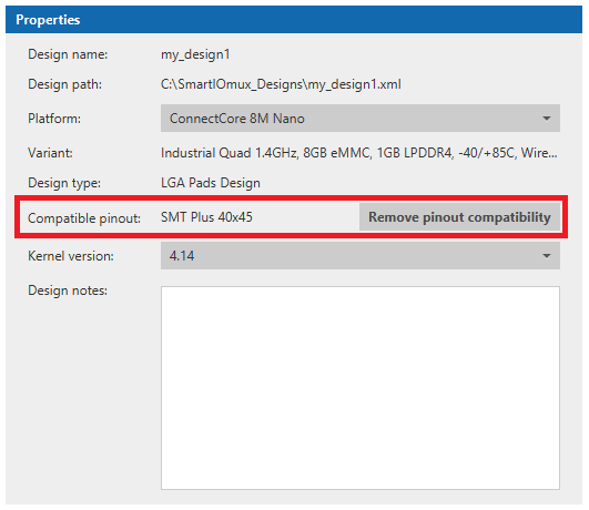
There is also a new entry (Compatible pinout) in the properties pane of cross-platform designs indicating the compatible pinout selected for the design:
Manage components
The way to work with cross-platform designs is exactly the same as standard designs. You can add, edit or remove components of the design at your choice. However, note that the Smart IOmux application is filtering and limiting the type and amount of components you can add, including the MUX configuration of each component and even the settings of those components. This is how Smart IOmux ensures the design keeps compatibility with all the platforms defined in the compatible pinout of the design.
If a component does not have a common pad mapping for all the platforms defined in the compatible pinout, it will appear in the list of available components but will be greyed-out. The only way to add that component to the design is to break the compatibility of the design.
Switch the platform of the design
Although the hardware of your project is the same for all platforms, the MUX configuration of each compatible platform must accommodate that hardware. For that reason, you can switch the base platform of cross-platform designs at any time while keeping the list of components and their configuration intact. This can be done in cross-platform designs and not in standard ones because the pad mapping of the components does not change.
To switch the platform of a design:
-
Select your design and go to the Configuration tab at the bottom of the pane.
-
Locate the Platform property of the design.
-
Open the drop-down and choose the platform you want to switch to. Remember that the list only contains the platforms that are defined in the compatible pinout selected for the design.
-
A confirmation dialog opens, indicating that all components and settings of the design except for electrical values will be kept intact. Click Yes to switch the platform.
When you switch the platform of a design, the electrical value of the pads cannot be kept because this value is platform-dependent and electrical values are set with the default value corresponding to that platform.
Break compatibility
Cross-platform designs allow you to add and use most of the primary interfaces of the ConnectCore platforms. However, there may be scenarios where you want to keep most of the design compatibility intact but add extra interfaces that can be populated later with link resistors in the hardware. You cannot perform this operation in a cross-platform design because the component you want to add may not be available, but you can do it by breaking the compatibility of the design.
| Be careful breaking the compatibility of a design, because this action cannot be undone. Digi recommends you make a new copy of a design and then break the compatibility on that copy. |
To break the compatibility of a design:
-
Open the cross-platform design.
-
Switch the platform of the design to the one you want to make modifications for.
-
Save a copy of the design using the Save design as option:
-
Select File > Save design as….
-
Enter the name and destination path of the new design.
-
Click Finish.
You are now working in a copy of the cross-platform design, keeping the original one intact.
-
-
Go to the Configuration tab at the bottom of the pane.
-
Locate the Compatible pinout property of the design and click the Remove pinout compatibility button. A confirmation dialog is displayed indicating that the action cannot be undone later.
-
Click Yes to remove the compatibility of the cross-platform design.
-
Save the design. The design is now a standard one, and therefore there is no limitation on the number of components you can add, their MUX configurations, or settings.
Repeat the process for all the platforms of your design you want to add extra functionality for.
